
SMD Capacitor
Introduction of SMD capacitorsChip capacitors are a kind of capacitor material. The full name of the chip capacitor is: multilayer (multilayer, laminated) chip ceramic capacitor (Multilayer Ceramic Capacitor, MLCC). There are two ways to express chip capacitors, one is expressed in inches, and the o
Introduction of SMD capacitors
Chip capacitors are a kind of capacitor material. The full name of the chip capacitor is: multilayer (multilayer, laminated) chip ceramic capacitor (Multilayer Ceramic Capacitor, MLCC). There are two ways to express chip capacitors, one is expressed in inches, and the other is expressed in millimeters. This article introduces Chinese chip capacitor manufacturers and product features and performance. The unit price of the product is favorable and the performance is stable.

Chip Capacitor Size
SMD capacitors are made of ceramic dielectric diaphragms with printed electrodes (internal electrodes) in a dislocation manner, and a ceramic chip is formed by one-time high-temperature sintering. Then seal the metal layer (external electrode) at both ends of the chip to form a monolithic structure, so it is also called a monolithic capacitor. There are two ways to express the size of chip capacitors, one is expressed in inches, and the other is expressed in millimeters. The series models of chip capacitors are 0402, 0603, 0805, 1206, 1210, 1808, 1812, 2010, 2225, 2512. These are in inches, 04 means length is 0.04 inches, 02 means width is 0.02 inches, other similar models dimensions (mm)
Imperial Dimensions Metric Dimensions Lengths and Tolerances Width and Tolerances Thickness and Tolerances
0402 1005 1.00±0.05 0.50±0.05 0.50±0.05
0603 1608 1.60±0.10 0.80±0.10 0.80±0.10
0805 2012 2.00±0.20 1.25±0.20 0.70±0.20 1.00±0.20 1.25±0.20
1206 3216 3.00±0.30 1.60±0.20 0.70±0.20 1.00±0.20 1.25±0.20
1210 3225 3.00±0.30 2.54±0.30 1.25±0.30 1.50±0.30
1808 4520 4.50±0.40 2.00±0.20 ≤2.00
1812 4532 4.50±0.40 3.20±0.30 ≤2.50
2220 5750 5.70±0.40 5.00±0.30 ≤2.50
2225 5763 5.70±0.50 6.30±0.50 ≤2.50
3035 7690 7.60±0.50 9.00±0.05 ≤3.00
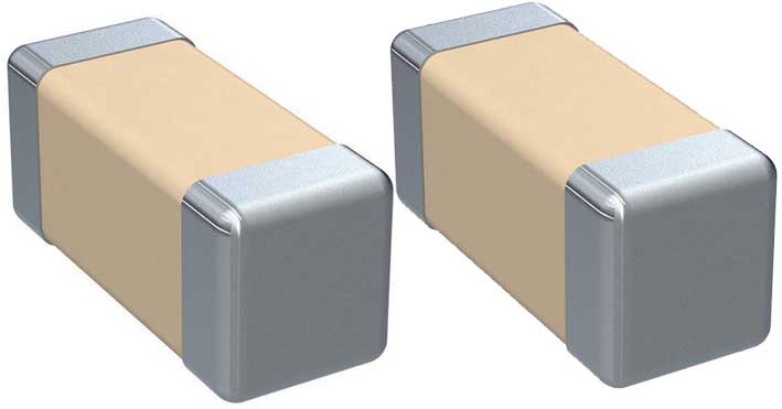
The color of chip capacitors is usually a little yellower than the cardboard box, and blue-gray. This will have different differences in the specific production process.
Naming rules for chip capacitors
The parameters included in the naming of the chip capacitor are: the size of the chip capacitor, the material used for the chip capacitor, the required accuracy, the required voltage, the required capacity, the terminal requirements and the packaging requirements. Generally, the parameters that need to be provided when ordering chip capacitors are the size, the required accuracy, the required voltage, the capacity value, and the required brand.
The naming of chip capacitors:
0805CG102J500NT 0805: refers to the size of the chip capacitor, expressed in inches. 08 means the length is 0.08 inches, 05 means the width is 0.05 inches. CG: It means the material required to make this kind of capacitor. This material is generally suitable for making capacitors less than 10000PF. 102: Refers to the capacity of the capacitor, the first two digits are effective figures, and the latter two represent how many zeros there are 102=10×100, that is, = 1000PF. J: It is required that the capacitance value of the capacitor achieve an error accuracy of 5%, and the dielectric material and error accuracy are paired. 500: It is required that the withstand voltage of the capacitor is 50V. Similarly, the first two digits of 500 are valid figures, and the latter refers to how many zeros there are. N: Refers to the material of the terminal, and the general terminal refers to the three-layer electrode (silver/copper layer), nickel, and tin. T: refers to the packaging method, and T refers to tape packaging. The color of chip capacitors is generally seen as yellow and blue-gray, which are a little lighter than the cardboard box, which will have different differences in the specific production process. There is no printing on the chip capacitor, which is related to his manufacturing process (the chip capacitor is sintered at high temperature, so there is no way to print on its surface), while the chip resistor is silk-screened.
SMD capacitor rated voltage from 4V to 4KV (DC). There are medium and high voltage chip capacitors and ordinary chip capacitors. When the rated voltage is 100V and above, it is classified as a medium and high voltage product. The voltage of the product series is 6.3V, 10V, 16V, 25V, 50V, 100V, 200V, 500V, 1000V, 2000V, 3000V, 4000V. It is expressed in millimeters, and the models of the chip capacitor series are 0201, 0402, 0603, 0805, 1206, 1210, 1812, 2010, 2225, etc. The materials of chip capacitors are generally divided into three types, NP0, X7R, Y5V. NP0 The electrical properties of this material are the most stable, almost unchanged with changes in temperature, voltage and time. It is suitable for high-frequency circuits with low loss and high stability requirements.
The capacity accuracy is about 5%, but this kind of material can only be used for small capacity, below the conventional 100PF, 100PF-1000PF can also be produced but the price is higher. The X7R material is less stable than NP0, but its capacity is higher than that of NP0, and the capacity accuracy is about 10%. The capacitance of such medium as Y5V has poor stability, and the capacity deviation is about 20%. It is sensitive to temperature and voltage, but this material can achieve high capacity and low price, and is suitable for circuits with little temperature change.
GRM0335C1E180JA01D | TDK | 18pF 0201 -5%~5% 25V C0G,NP0 | ||||||
GRM0335C1E2R7CA01D | 2.7pF 0201 -0.25pF~0.25pF 25V C0G,NP0 | |||||||
GRM0335C1E4R7BA01D | 4.7pF 0201 -0.1pF~0.1pF 25V C0G,NP0 | |||||||
GRM0335C1H150GA01D | 15pF 0201 -2%~2% 50V C0G,NP0 | |||||||
GRM0335C1H1R8CA01D | 1.8pF 0201 -0.25pF~0.25pF 50V C0G,NP0 | |||||||
GRM0335C1H390JA01D | 39pF 0201 -5%~5% 50V C0G,NP0 | |||||||
GRM0335C1H3R9CA01D | 3.9pF 0201 -0.25pF~0.25pF 50V C0G,NP0 | |||||||
GRM0335C1H470JA01D | 47pF 0201 -5%~5% 50V C0G,NP0 | |||||||
GRM0335C1H7R0CA01D | 7pF 0201 -0.25pF~0.25pF 50V C0G,NP0 | |||||||
GRM0335C1H8R2BA01D | 8.2pF 0201 -0.1pF~0.1pF 50V C0G,NP0 | |||||||
GRM033R60J223KE01D | 22nF 0201 -10%~10% 6.3V X5R | |||||||
GRM033R61A223KE84D | 22nF 0201 -10%~10% 10V X5R | |||||||
GRM033R61A225ME47D | 2.2?F 0201 -20%~20% 10V X5R | |||||||
GRM033R61E104KE14D | 0.1?F 0201 -10%~10% 25V X5R | |||||||
GRM033R71C102KA01D | 1nF 0201 -10%~10% 16V X7R | |||||||
GRM033R71E101KA01D | 100pF 0201 -10%~10% 25V X7R | |||||||
GRM033R71E152KA01D | 1.5nF 0201 -10%~10% 25V X7R | |||||||
GRM033R71E472KE14D | 4.7nF 0201 -10%~10% 25V X7R | |||||||
GRM1555C1E120JA01D | 12pF 0402 -5%~5% 25V C0G,NP0 | |||||||
GRM1555C1E2R2BA01D | 2.2pF 0402 -0.1pF~0.1pF 25V C0G,NP0 | |||||||
GRM1555C1H110JA01D | 11pF 0402 -5%~5% 50V C0G,NP0 | |||||||
GRM1555C1H1R0WA01D | 1pF 0402 -0.05pF~0.05pF 50V C0G,NP0 | |||||||
GRM1555C1H1R2WA01D | 1.2pF 0402 -0.05pF~0.05pF 50V C0G,NP0 | |||||||
GRM1555C1H1R8WA01D | 1.8pF 0402 -0.05pF~0.05pF 50V C0G,NP0 | |||||||
GRM1555C1H1R9WA01D | 1.9pF 0402 -0.05pF~0.05pF 50V C0G,NP0 | |||||||
GRM1555C1H271GA01D | 270pF 0402 -2%~2% 50V C0G,NP0 | |||||||
GRM1555C1H2R2CA01D | 2.2pF 0402 -0.25pF~0.25pF 50V C0G,NP0 | |||||||
GRM1555C1H3R3CA01D | 3.3pF 0402 -0.25pF~0.25pF 50V C0G,NP0 | |||||||
GRM1555C1H470GA01D | 47pF 0402 -2%~2% 50V C0G,NP0 | |||||||
GRM1555C1H510JA01D | 51pF 0402 -5%~5% 50V C0G,NP0 | |||||||
GRM1555C1H560FA01D | 56pF 0402 -1%~1% 50V C0G,NP0 | |||||||
GRM1555C1H6R8WA01D | 6.8pF 0402 -0.05pF~0.05pF 50V C0G,NP0 | |||||||
GRM155R61A105KE01D | 1?F 0402 -10%~10% 10V X5R | |||||||
GRM155R61A683KA01D | 68nF 0402 -10%~10% 10V X5R | |||||||
GRM155R61C225KE11D | 2.2?F 0402 -10%~10% 16V X5R | |||||||
GRM155R61E224KE01D | 0.22?F 0402 -10%~10% 25V X5R | |||||||
GRM155R71E103JA01D | 10nF 0402 -5%~5% 25V X7R | |||||||
GRM155R71E223KA61D | 22nF 0402 -10%~10% 25V X7R | |||||||
GRM155R71E333KA88D | 33nF 0402 -10%~10% 25V X7R | |||||||
GRM155R71H182KA01D | 1.8nF 0402 -10%~10% 50V X7R | |||||||
GRM155R71H272KA01D | 2.7nF 0402 -10%~10% 50V X7R | |||||||
GRM155R71H332KA01D | 3.3nF 0402 -10%~10% 50V X7R | |||||||
GRM155R72A152KA01D | 1.5nF 0402 -10%~10% 100V X7R | |||||||
GRM185R61A475ME11D | 4.7UF 0603 -20%~20% 10V X5R | |||||||
GRM1882C1H121JA01D | 120pF 0603 -5%~5% 50V | |||||||
GRM1882C1H681JA01D | 680pF 0603 -5%~5% 50V CH | |||||||
GRM1885C1H102FA01D | 1nF 0603 -1%~1% 50V C0G,NP0 | |||||||
GRM1885C1H130JA01D | 13pF 0603 -5%~5% 50V C0G,NP0 | |||||||
GRM1885C1H1R8BA01D | 1.8pF 0603 -0.1pF~0.1pF 50V C0G,NP0 | |||||||
GRM1885C1H200JA01D | 20pF 0603 -5%~5% 50V C0G,NP0 | |||||||
GRM1885C1H220GA01D | 22pF 0603 -2%~2% 50V C0G,NP0 | |||||||
GRM1885C1H221JA01D | 220pF 0603 -5%~5% 50V C0G,NP0 | |||||||
GRM1885C1H2R4CA01D | 2.4pF 0603 -0.25pF~0.25pF 50V C0G,NP0 | |||||||
GRM1885C1H300JA01D | 30pF 0603 -5%~5% 50V C0G,NP0 | |||||||
GRM1885C1H330FA01D | 33pF 0603 -1%~1% 50V C0G,NP0 | |||||||
GRM1885C1H330JA01D | 33pF 0603 -5%~5% 50V C0G,NP0 | |||||||
GRM1885C1H360JA01D | 36pF 0603 -5%~5% 50V C0G,NP0 | |||||||
GRM1885C1H3R3CA01D | 3.3pF 0603 -0.25pF~0.25pF 50V C0G,NP0 | |||||||
GRM1885C1H561FA01D | 560pF 0603 -10%~10% 50V C0G,NP0 | |||||||
GRM1885C1H5R0CA01D | 5pF 0603 -0.25pF~0.25pF 50V C0G,NP0 | |||||||
GRM1885C1H620JA01D | 62pF 0603 -5%~5% 50V C0G,NP0 | |||||||
GRM1885C1H822JA01D | 8.2nF 0603 -5%~5% 50V C0G,NP0 | |||||||
GRM1885C2A4R7CA01D | 4.7pF 0603 -0.25pF~0.25pF 100V C0G,NP0 | |||||||
GRM188R60J106KE47D | 10uF 0603 -10%~10% 6.3V X5R | |||||||
GRM188R61A335KE15D | 3.3uF 0603 -10%~10% 10V X5R | |||||||
GRM188R61C105KA12D | 1uF 0603 -10%~10% 16V X5R | |||||||
GRM188R61H104KA93D | 0.1uF 0603 -10%~10% 50V X5R | |||||||
GRM188R71C222KA01D | 2.2nF 0603 -10%~10% 16V X7R | |||||||
GRM188R71E393KA01D | 39nF 0603 -10%~10% 25V X7R | |||||||
GRM188R71H104JA93D | 0.1uF 0603 -5%~5% 50V X7R | |||||||