
Capacitor Supply
Introduction to CapacitorsCapacitors are components that store electricity and electrical energy (potential energy). A conductor surrounded by another conductor, or the electric field lines emitted by one conductor all terminate in another conductor, is called a capacitor.The capacitance formula for
Introduction to Capacitors
Capacitors are components that store electricity and electrical energy (potential energy). A conductor surrounded by another conductor, or the electric field lines emitted by one conductor all terminate in another conductor, is called a capacitor.
The capacitance formula for a parallel plate capacitor is:
Among them, UA-UB is the potential difference between the two parallel plates, εr is the relative permittivity, k is the electrostatic force constant, S is the facing area of the two plates, and d is the distance between the two plates. Explanation: The electric field in a parallel plate capacitor is a uniform electric field.
Capacitance is not the same as capacitor. Capacitance is a basic physical quantity, the symbol C, and the unit is F (farad).
General formula C=Q/U, special formula for parallel plate capacitors: electric field strength between plates E=U/d.
 |  |  |
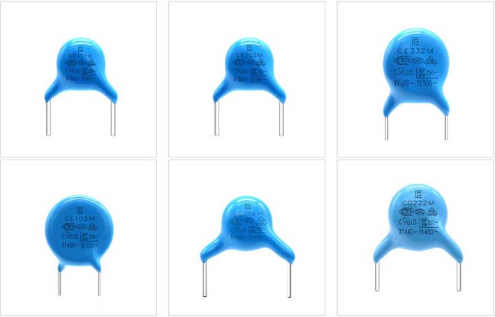
| The use and characteristics of Y safety capacitors: According to the AC capacitor standard and passed the safety certification, it is ideal for line bypass, coupling and line jumper. It is used as AC circuit filter and primary-secondary coupling of switching power supply and AC adapter, and secondly used for DA insulation and noise reduction of transformerless DAA modem. ● Passed IEC and multinational safety standard certification ● Compact size, sealed with flame retardant epoxy resin ● RoHS Compliant | The use and characteristics of X safety capacitors: It is mainly used in anti-interference occasions such as various power supply cross-lines, etc., with low high-frequency loss and small internal temperature rise, plastic shell (UL94 V-0), and flame-retardant epoxy resin filling. ● Passed IEC and multinational safety standard certification ● Compact size, sealed with flame retardant epoxy resin ● RoHS Compliant | The use and characteristics of film capacitors: Widely used in high-frequency, DC, AC and pulse circuits, non-inductive structure, less loss, and small internal temperature rise. Can withstand high pulse, high current, high frequency resistance 100KHZ, less capacity change, negative temperature coefficient |
The main parameters of the capacitor
(1) Nominal capacitance is the capacitance marked on the capacitor. However, there is a deviation between the actual capacitance of the capacitor and the nominal capacitance, and there is a corresponding relationship between the accuracy level and the allowable error. Generally, capacitors are commonly used in grades I, II, and III, and electrolytic capacitors are used in grades IV, V, and VI to indicate capacity accuracy, which is selected according to the application. The capacitance value of an electrolytic capacitor depends on the impedance it presents when working under AC voltage, and the capacitance value will change with the change of operating frequency, temperature, voltage and measurement method. The unit of capacitance is F (law).
Since a capacitor is a "container" for storing charges, there is a problem of "capacity". In order to measure the ability of a capacitor to store charge, the physical quantity of capacitance is determined. Capacitors must be under the action of an applied voltage to store charge. Different capacitors may also store different amounts of charge under voltage. According to international uniform regulations, when a DC voltage of 1 volt is applied to a capacitor, the amount of charge it can store is the capacitance of the capacitor (that is, the amount of electricity per unit voltage), expressed in C. The basic unit of capacitance is Farad (F). Under the action of a DC voltage of 1 volt, if the charge stored in the capacitor is 1 coulomb, the capacitance is determined as 1 farad, and the farad is represented by the symbol F, 1F=1Q/V. In practical applications, the capacitance of a capacitor is often much smaller than 1 Farad, and smaller units are commonly used, such as millifarad (mF), microfarad (μF), nanofarad (nF), picofarad (pF), etc. Their relationship is: 1 microfarad is equal to one millionth of a farad; 1 picofarad is equal to one millionth of a microfarad, namely:
1 farad (F) = 1000 millifarad (mF); 1 millifarad (mF) = 1000 microfarad (μF); 1 microfarad (μF) = 1000 nanofarad (nF); 1 nanofarad (nF) = 1000 picofarads (pF); namely: 1F = 1000000μF; 1μF = 1000000pF.
(2) The rated voltage is the highest DC voltage that can be continuously applied to the capacitor at the lowest ambient temperature and the rated ambient temperature. If the operating voltage exceeds the withstand voltage of the capacitor, the capacitor will be broken down and damaged. In practice, as the temperature increases, the withstand voltage value will become lower.
(3) Insulation resistance. The DC voltage is added to the capacitor to generate a leakage current, and the ratio between the two is called the insulation resistance. When the capacitance is small, its value mainly depends on the surface state of the capacitor; when the capacitance is greater than 0.1μF, its value mainly depends on the medium. In general, the higher the insulation resistance, the better.
(4) Loss. Under the action of an electric field, the energy consumed by heat in a unit time is called loss. The loss is related to the frequency range, dielectric, conductance, resistance of the metal part of the capacitor, etc.
(5) Frequency characteristics. As the frequency increases, the capacitance of a general capacitor shows a decreasing trend. When the capacitor works below the resonant frequency, it behaves as capacitive; when it exceeds its resonant frequency, it behaves as inductive, and at this time it is not a capacitor but an inductance. Therefore, it is necessary to avoid capacitors operating above the resonant frequency.