
Custom Inductors
What is inductance?Inductance is a property of a closed loop and a physical quantity. When the current passes through the coil, a magnetic field induction is formed in the coil, and the induced magnetic field will generate an induced current to resist the current passing through the coil. It is a ci
What is inductance?
Inductance is a property of a closed loop and a physical quantity. When the current passes through the coil, a magnetic field induction is formed in the coil, and the induced magnetic field will generate an induced current to resist the current passing through the coil. It is a circuit parameter that describes the induced electromotive force effect in this coil or in another coil due to the change of coil current. Inductance is the general term for self-inductance and mutual inductance. A device that provides inductance is called an inductor.
Definition of inductance
A property of a conductor measured as the ratio of the electromotive force or voltage induced in the conductor to the rate of change of the current producing that voltage. A constant current creates a stable magnetic field, and a constantly changing current (AC) or fluctuating DC creates a changing magnetic field, which in turn induces an electromotive force in a conductor in that magnetic field. The magnitude of the induced electromotive force is proportional to the rate of change of current. The proportionality factor is called inductance, represented by the symbol L, and the unit is Henry (H).
Inductance is a property of a closed loop in that as the current through the closed loop changes, an electromotive force appears to resist the change in current. This inductance is called self-inductance and is a property of the closed loop itself. Assuming that the current changes in one closed loop, an electromotive force is generated in another closed loop due to induction. This inductance is called mutual inductance.
self inductance inductance
When a current flows through the coil, a magnetic field is created around the coil. When the current in the coil changes, the magnetic field around it changes accordingly. This changing magnetic field can cause the coil itself to produce an induced electromotive force (induced electromotive force) (electromotive force is used to represent the terminal voltage of an ideal power supply for active components), which is self-induction.
mutual inductance
When two induction coils are close together, the change in magnetic field of one induction coil affects the other induction coil and this effect is mutual inductance. The magnitude of the mutual inductance depends on the degree of coupling between the self-inductance of the choke coil and the two choke coils. The components manufactured according to this principle are called transformers.
The development history of inductors
The most primitive inductor is the iron core coil used by British M. Faraday in 1831 to discover the phenomenon of electromagnetic induction. In 1832, J. Henry of the United States published a paper on the phenomenon of self-induction. People call the unit of inductance Henry, or Henry for short. In the mid-19th century, inductors found practical applications in devices such as telegraphs and telephones. The inductors used by H.R. Hertz in Germany in 1887 and N. Tesla in the United States in 1890 are very famous, and they are called Hertz coils and Tesla coils respectively.
 |  |  |
| High current filter choke There are two types of magnetic rod inductors: horizontal and vertical. The magnetic rod sensor is to wind the ordinary enameled wire or high temperature enameled wire directly on the rod-shaped magnetic core, the coil body is dipped in glue (varnish), and the pins are tinned. High-current design is adopted to adapt to high-current circuit boards. It has the advantages of small size, light weight, firm structure (vibration resistance, impact resistance), good moisture resistance, convenient installation, and various specifications to choose from. Widely used in power supplies, power amplifiers, noise filtering of switching circuits, controlled rectifiers and thyristor control circuits, and output chokes. RoHS compliant, lead-free soldering technology and 100% lead-free, and provide more competitive price and fast delivery service. If you need special specifications and types, please contact YAXUN inductance business. ① Product type: high current filter choke coil. | Iron Powder Core Differential Mode Inductor Iron powder core differential mode inductor is a kind of soft magnetic material that is not saturated under the soft magnetic field, which is made of high-purity reduced iron powder or base iron powder, coated with surface insulation and mixed with binder. It has good DC superposition characteristics. The production process is simple, and the price is the lowest among all kinds of metal magnetic powder cores. Toroidal coil inductance is the most ideal shape in inductance theory. With a closed magnetic circuit, there are few EMI problems, and the magnetic circuit is fully utilized, easy to calculate, low cost, and almost all theoretical benefits are attributed to the toroidal coil inductance. Mainly used in power supplies, switching circuits, controlled rectifiers and thyristor control circuits, output chokes and EMI/RFI chokes, and other filters. The toroidal iron core not only has excellent magnetic properties, but also has many mechanical advantages: The pressure between sheets can be strictly controlled, and can reach 95% of the same level. Using impregnation technology, the iron core can be made into a solid whole, and the image will not change during winding and processing; Since the toroidal core is very strong, the influence of magnetostrictive force is reduced, thus reducing vibration and audible noise. Differential mode inductors are in compliance with ROHS specifications, lead-free lead-free standards, provide complete coil inductor size, complete range of inductance, and can be manufactured according to customer needs. ① Product type: TC high current filter choke coil. ② Style: core size and material. ③ Outlet pin shape: Refer to "Illustration and Dimensions" for details on the outlet pin mark. ④ Inductance value: For example, "6R8" means 6.8 uH. ⑤ Inductance tolerance: "M": +20%; "K": +10%; "J": +5%. ⑥ UL or PVC heat shrinkable sleeve protection. | Amorphous Nanocrystalline Common Mode Inductor Nanocrystalline materials have much higher saturation magnetic flux density than ferrite, higher initial permeability, and excellent impedance-frequency characteristics. Excellent temperature stability is widely used to make common mode inductors. Due to the higher magnetic permeability of amorphous and nanocrystalline, it can have high inductance at low frequencies. When winding the same inductance with the same size as ferrite, the number of turns is less than that of ferrite, so it has smaller distributed capacitance and the highest resonance frequency. Nanocrystalline is more expensive than ferrite, but due to fewer winding turns and less copper, the actual winding cost is reduced, and it has higher production efficiency. Distributed capacitance cannot be ignored when designing common mode inductors. Distributed capacitance includes the capacitance of the winding itself and the capacitance between the winding and the magnetic core, and the body capacitance of the winding includes the capacitance between turns and layers. The capacitance reflected to both ends of the winding is related to the interlayer capacitance and the potential difference between the layers. In the multi-layer winding of common mode inductors, the potential difference between turns is small, but the potential difference between layers is relatively large, resulting in a greater influence of interlayer capacitance on the inherent capacitance of the coil. Therefore, it is the best choice to use amorphous and nanocrystalline to reduce the number of winding layers. |
Inductor Structure
Inductors are generally composed of skeletons, windings, shields, packaging materials, magnetic cores or iron cores.
1. Inductor skeleton: the skeleton generally refers to the support for winding the coil. Some larger fixed inductors or adjustable inductors (such as oscillating coils, choke coils, etc.), most of which are enameled wires (or yarn-covered wires) wrapped around the skeleton. Then put the magnetic core or copper core, iron core, etc. into the inner cavity of the skeleton to increase its inductance. The skeleton is usually made of plastic, bakelite, and ceramics, and can be made into different shapes according to actual needs. Small inductors (such as color-coded inductors) generally do not use a bobbin, but directly wind the enameled wire on the magnetic core. Air-core inductors (also known as bodiless coils or air-core coils, mostly used in high-frequency circuits) do not require magnetic cores, skeletons, and shielding covers. Instead, it is wound on the mold first, and then the mold is taken off, and a certain distance is drawn between each coil of the coil.
2. Winding: Winding refers to a group of coils with specified functions, which is the basic component of inductors. There are single-layer and multi-layer windings. There are two forms of single-layer winding: dense winding (the wires are next to each other when winding) and inter-winding (there is a certain distance between each wire when winding);
There are many kinds of multilayer windings, such as layered flat winding, random winding, and honeycomb winding.
3. Magnetic core and magnetic rod: The magnetic core and magnetic rod are generally made of nickel-zinc ferrite (NX series) or manganese-zinc ferrite (MX series). It has "I" shape, column shape, hat shape, "E" shape, pot shape and other shapes.
4. Iron core: Iron core materials mainly include silicon steel sheet, permalloy, etc., and its shape is mostly "E" type.
5. Shielding cover: In order to prevent the magnetic field generated by some inductors from affecting the normal operation of other circuits and components, a metal screen cover (such as the oscillating coil of a semiconductor radio, etc.) is added to it. Using shielded inductors will increase the loss of the coil and reduce the Q value.
6. Packaging materials: After some inductors (such as color code inductors, color ring inductors, etc.) are wound, the coils and magnetic cores are sealed with packaging materials. The packaging material is plastic or epoxy resin.
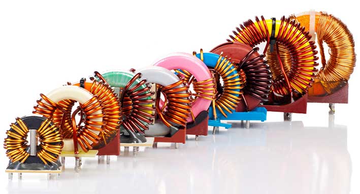
Inductor Copper Coil
Inductance is the ratio of the magnetic flux of the wire to the current that produces this flux when an alternating current is passed through the wire. When a DC current passes through the inductor, only fixed magnetic lines of force appear around it, which do not change with time;
However, when an alternating current is passed through the coil, magnetic lines of force that change with time will appear around it. According to Faraday's law of electromagnetic induction—magnetism generates electricity, the changing magnetic lines of force will generate an induced potential at both ends of the coil, which is equivalent to a "new power supply". When a closed loop is formed, the induced potential will generate an induced current. According to Lenz's law, it is known that the total amount of magnetic force lines generated by induced current should try to prevent the change of magnetic force lines. The change of the magnetic field line comes from the change of the external alternating power supply, so from the objective effect, the inductance coil has the characteristic of preventing the current change in the alternating current circuit. The inductance coil has characteristics similar to the inertia in mechanics, and is named "self-induction" in electricity. Usually at the moment when the knife switch is pulled or turned on, a spark will occur, which is caused by the high induced potential generated by the self-inductance phenomenon.
In short, when the inductance coil is connected to the AC power supply, the magnetic field lines inside the coil will change with the alternating current, causing the coil to generate electromagnetic induction. This electromotive force generated by the change of the current of the coil itself is called "self-induced electromotive force". It can be seen that the inductance is only a parameter related to the number of turns, size, shape and medium of the coil. It is a measure of the inertia of the inductor coil independent of the applied current.
Substitution principle: 1. The inductance coil must be replaced with the original value (the number of turns is equal and the size is the same). 2. SMD inductors only need to be the same size, and can also be replaced by 0 ohm resistors or wires.
Inductor Characteristics
The characteristics of an inductor are just the opposite of those of a capacitor. It has the property of blocking alternating current and allowing direct current to pass smoothly. The resistance when the DC signal passes through the coil is that the resistance voltage drop of the wire itself is very small; When the AC signal passes through the coil, a self-induced electromotive force will be generated at both ends of the coil, and the direction of the self-induced electromotive force is opposite to the direction of the applied voltage, which hinders the passage of AC. Therefore, the characteristic of an inductor is to pass DC and block AC. The higher the frequency, the greater the coil impedance. Inductors often work together with capacitors in circuits to form LC filters, LC oscillators, etc. In addition, people also use the characteristics of inductance to manufacture choke coils, transformers, relays, etc.
Direct current: means that the inductor is in a closed state to direct current. If the resistance of the coil of the inductor is ignored, then DC can pass through the inductor "unimpeded". For DC, the resistance of the coil itself has very little resistance to DC, so it is often ignored in circuit analysis.
AC resistance: When the AC passes through the inductance coil, the inductor has a hindering effect on the AC, and it is the inductive reactance of the inductance coil that hinders the AC.
Inductance measurement method
Two types of instruments for inductance measurement: RLC measurement (resistance, inductance, and capacitance can be measured) and inductance measuring instruments.
Measurement of inductance: no-load measurement (theoretical value) and measurement in an actual circuit (actual value). Due to the fact that the actual circuit used by the inductor is too much, it is difficult to give an example. Only measurements under no-load conditions are interpreted. Inductance measurement steps (RLC measurement):
1. Familiar with the operating rules (instructions) and precautions of the instrument.
2. Turn on the power and prepare for 15-30 minutes.
3. Select the L file, and select to measure the inductance.
4. Clamp the two clips to each other and reset to zero.
5. Clamp the two ends of the inductance with two clips, read the value and record the inductance.
6. Repeat steps 4 and 5 to record the measured values. There must be 5-8 data.
7. Compare several measured values: if the difference is not large (0.2μH), take the average value, and remember the theoretical value of the inductance; if the difference is too large (0.3μH), repeat steps 2-6 until the theoretical value of the inductance is obtained value.
Because the inductance parameters measured by different instruments will be somewhat different. Therefore, it is necessary to be familiar with the use of measuring instruments before making measurements, understand the specific functions of the instruments, and then operate according to the operating instructions of the instruments.
Circuit Diagram Design of Inductor
Labeling method
1. Direct marking method: mark the inductance of the inductance coil, the allowable error and the maximum operating current and other main parameters directly on the shell of the inductance coil with numbers and words.
2. Color scale method: use the color circle to represent the inductance, the unit is mH, the first and second digits represent significant figures, the third digit represents the magnification, and the fourth digit is the error.
Good or bad judgment of inductance
1. Inductance measurement: Turn the multimeter to the buzzer diode position, put the test leads on the two pins, and see the reading of the multimeter.
2. Judgment of good or bad: The reading of the chip inductor should be zero at this time. If the reading of the multimeter is too large or infinite, it means that the inductor is damaged.
For coils with more turns and thinner wire diameters, the readings will reach tens to hundreds. Usually the DC resistance of the coil is only a few ohms. The damage is manifested as heating or obvious damage to the induction magnetic ring. If the inductance coil is not seriously damaged and cannot be determined, it can be judged by measuring its inductance with an inductance meter or by replacing it.
Considerations for Inductors
1> Inductive components: the core and winding are prone to inductance changes due to temperature rise. It should be noted that the body temperature must be within the range of use specifications.
2> Winding of the inductor: It is easy to form an electromagnetic field after the current passes through. When placing components, care should be taken to keep adjacent inductors away from each other, or the winding groups are at right angles to each other, so as to reduce the mutual inductance.
3> Between the winding layers of the inductor: especially multi-turn thin wires, there will also be gap capacitance, causing high-frequency signal bypass, and reducing the actual filtering effect of the inductor.
4> When testing the inductance value and Q value with an instrument, in order to obtain correct data, the test lead should be as close as possible to the component body.