
Photocoupler Manufacturer
What is an optocoupler?A photocoupler is an electrical-optical-electrical conversion device that transmits electrical signals through light. It consists of two parts: the light source and the light receiver. The light-emitting source and the light-receiving device are assembled in the same airtight
What is an optocoupler?
A photocoupler is an electrical-optical-electrical conversion device that transmits electrical signals through light. It consists of two parts: the light source and the light receiver. The light-emitting source and the light-receiving device are assembled in the same airtight casing, and they are separated by transparent insulators. The pin of the light source is the input end, and the pin of the light receiver is the output end. The common light source is a light-emitting diode, and the light receiver is a photodiode, phototransistor, etc.
Opto-isolator (Opto-isolator, or optical coupler, abbreviated as OC), also known as optocoupler or optical isolator and opto-isolator, referred to as optocoupler. Photocouplers are a group of electronic devices that transmit electrical signals with light as the medium. Its function is to maintain a good isolation between the input and output of electrical signals at ordinary times, and to transmit electrical signals through the isolation layer when necessary.
 |  |  |
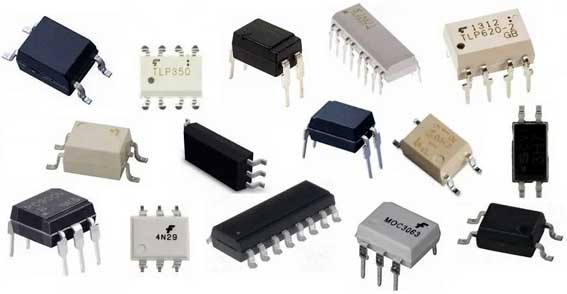
| EHAOAN optocoupler made in China Optocoupler output category: Transistor, Gate Driver, TRIAC, Relay, High Speed, Isolation AP; Package type: number of pins 4-16PIN, creepage distance 4-10mm; Applications: power supplies, chargers, smart meters, small appliances, solar conversion, battery management systems, industrial controls, dimmers; Optocoupler packaging technology: up and down opposite type, two-time plastic sealing plane type, one-time plastic sealing plane type; Compliant with RoHS Directive; | Phototransistor Optocoupler -EHAOAN optocoupler 814,816,817,357 and other series. - Halogen Free, > Current Transfer Ratio (CTR: 50~600%, at IF = 5mA. -Operating temperature up to +110C - creepage distance > 7.62mm; - Applied to the transmission of signals between circuits of different potentials and impedances; - RoHS Compliant; | High speed optocoupler EHAOAN high-speed optocoupler has fast switching speed, and the response speed of high-speed optocoupler reaches the order of ns, which greatly expands the application of optocoupler in digital signal processing. |
Introduction to photocoupler components
The photocoupler can transmit signals between two circuits that do not share the same ground, even if there is high voltage between the two circuits, it will not be affected. The input-to-output withstand voltage of commercial optocoupler components can reach 10kV, and the voltage change rate can be as fast as 10kV/μs.
Photocouplers can be divided into two types: analog and digital, both of which are composed of light emitters and light detectors. Optical emitters and optical detectors are often integrated into the same package, but there is no electrical or physical connection between them other than the light beam.
A common optocoupler consists of a light emitting diode (LED) and a phototransistor (LED) in an opaque package. Other combinations are LED-photodiode, LED-LASCR, and bulb-photoresistor. Optocouplers generally transmit digital signals, but with some technologies, optocouplers can also be used to transmit analog signals.
Optocoupler components are widely used in electrical isolation, level conversion, drive circuits and industrial communications. However, due to the problem of parasitic input and output capacitance, its Common-Mode Transient Immunity (Common-Mode Transient Immunity) capability is weak. In addition, its speed is limited, the power consumption of optocoupler components is high, and components are prone to aging.
Optocouplers use light as a medium to transmit electrical signals. It has a good isolation effect on input and output electrical signals, so it is widely used in various circuits. At present, it has become one of the most diverse and widely used optoelectronic devices. An optocoupler generally consists of three parts: light emission, light reception, and signal amplification. The input electrical signal drives the light-emitting diode (LED) to emit light of a certain wavelength, which is received by the photodetector to generate a photocurrent, which is further amplified and output. This completes the electrical-optical-electrical conversion, thereby playing the role of input, output, and isolation. Since the input and output of the optocoupler are isolated from each other, and the electrical signal transmission has the characteristics of unidirectionality, it has good electrical insulation ability and anti-interference ability.
A photocoupler is a semiconductor optoelectronic device that encapsulates a light-emitting device and a photosensitive device in the same housing, and transmits electrical signals through the conversion of electricity → light → electricity. Wherein, the light-emitting devices are generally light-emitting diodes. There are many types of photosensitive devices, in addition to photodiodes, there are phototransistors, photoresistors, photothyristors, etc. According to different requirements, optocouplers can be combined into many series of optocouplers from different types of light emitting devices and photosensitive devices.
The overview diagram shows a typical optocoupler drive circuit. In this example, the 5V secondary output on the right will be controlled by the PWM of the left primary circuit.
Comparator A1 compares the reference voltage of ZD1 (node A) with the output voltage of the voltage divider circuit R7 and R8. Therefore, controlling the conduction state of Q2 can define the current of the light-emitting diode D1 and the collector current of the phototransistor Q1 through optical coupling. Q1 then defines the pulse width and output voltage, compensating for any tendency to change the output voltage.
As the usage time of the optocoupler increases and the transfer ratio gain decreases, it is necessary to provide sufficient driving current margin for Q2 in order to prevent control failure. There are many types of optocouplers, such as photodiode type, phototransistor type, photoresistor type, light-controlled thyristor type, photoelectric Darlington type, integrated circuit type, etc. (The shape has metal round shell package, plastic package dual in-line plug, etc.).
How Optocouplers Work
structure
The main structure of the photocoupler is to assemble the light-emitting device and the light-receiving device in a closed package, and then use the pins of the light-emitting device as the input end, and the pins of the light receiver as the output end. When a power signal is applied to the input terminal, the light emitting device emits light. In this way, the photoreceiving device generates photocurrent after being illuminated due to the photosensitivity effect and outputs it from the output terminal. In this way, the electrical signal transmission with "light" as the medium is realized, and the input and output ends of the device are electrically insulated. In this way, a new type of semiconductor optoelectronic device that transmits signals through light is formed. The packaging forms of optocouplers generally include: tubular, dual in-line and optical fiber connection. It has small size, long service life, wide working temperature range and strong anti-interference performance. It has the advantages of no contact and complete electrical isolation between input and output.
features
The main features of optocoupler are as follows:
① The optical signal is transmitted in one direction, and the output signal has no feedback to the input terminal, which can effectively block the electrical connection between circuits or systems, but does not cut off the signal transmission between them.
② The isolation performance is good, and the electrical isolation is completely realized between the input terminal and the output terminal.
③ The optical signal is not interfered by electromagnetic waves, and the work is stable and reliable.
④ The spectral matching between the light emitting device and the photosensitive device is very ideal, the response speed is fast, and the transmission efficiency is high. The time constant of optocoupler devices is usually on the order of microseconds or even nanoseconds.
⑤ Strong anti-common-mode interference ability, can well suppress interference and eliminate noise.
⑥ Non-contact, long service life, small size, strong impact resistance.
⑦ Easy to connect with logic circuit.
⑧ Wide operating temperature range, in line with industrial and military temperature standards.
Since the input terminal of the photocoupler is a light-emitting device, the light-emitting device is an impedance current-driven device, and the noise is a high internal resistance micro-current voltage signal. Therefore, the common mode rejection ratio of the optocoupler device is very large, and the optocoupler device can well suppress interference and eliminate noise. It is used as an interface component for signal isolation in computer digital communication and real-time control circuits, which can greatly increase the reliability of computer work. As a terminal isolation element in long-line information transmission, it can greatly improve the signal-to-noise ratio. Therefore, it has been widely used in various circuits. At present, it has become one of the most diverse and widely used optoelectronic devices.
The insulation between the input and output terminals is generally greater than 10Ω, and the withstand voltage can generally exceed 1kV, and some can even reach above 10kV. Due to the unidirectionality of "light" transmission, there will be no feedback phenomenon when the signal is unidirectionally transmitted from the light source to the optical receiver, and the output signal will not affect the input terminal. Since the light-emitting device (gallium arsenide infrared diode) is an impedance current-driven device, noise is a voltage signal with high internal resistance and micro-current. Therefore, the common mode rejection ratio of the optocoupler device is very large, so the optocoupler device can suppress interference and eliminate noise very well. It is used as an interface component for signal isolation in computer digital communication and real-time control circuits, which can greatly increase the reliability of computer work. As a terminal isolation element in long-line information transmission, it can greatly improve the signal-to-noise ratio. Therefore, it has been widely used in various circuits. At present, it has become one of the most diverse and widely used optoelectronic devices.
Optocoupler Testing
1. Use a multimeter to judge whether it is good or bad, disconnect the power supply at the input end, and measure the resistance of pins 1 and 2 with R×1k gear. The forward resistance is hundreds of ohms, the reverse resistance is tens of thousands of ohms, and the resistance between pins 3 and 4 should be infinite. Any group between pins 1 and 2 and pins 3 and 4 has an infinite resistance value. After the input terminal is powered on, the resistance of pins 3 and 4 is very small. Adjust RP, the resistance between pins 3 and 4 changes, indicating that the component is good. Note: R×10k file cannot be used, otherwise the launch tube will be broken down.
2. Simple test circuit, when the power is turned on, the LED does not light up, press SB, the LED will light up. Adjusting RP and the luminous intensity of LED will change, indicating that the photocoupler under test is good.
Application of optocoupler
As a terminal isolation element in long-line information transmission, it can greatly improve the signal-to-noise ratio. Therefore, it has been widely used in various circuits. At present, it has become one of the most diverse and widely used optoelectronic devices.
Photocoupler switching circuit
For switching circuits, it is often required to have good electrical isolation between the control circuit and the switching circuit, which is difficult to achieve for general electronic switches. But it is easy to implement with optocoupler. The circuit shown in (a) in Figure 1 is a simple switching circuit composed of photocouplers.
In Figure 1(a), when there is no pulse signal input, the triode BG is in the cut-off state, and the light-emitting diode has no current flowing through it and does not emit light. Then the resistance at both ends of a and b is very large, which is equivalent to the switch being "off". When a pulse signal is applied to the input end, BG is turned on, and the light-emitting diode emits light, and the resistance at both ends of a and b becomes very small, which is equivalent to the switch "on". Therefore, it is said that the switch is blocked when there is no signal, and it is in the normally open state.
The circuit shown in (b) in Figure 1 is in the "normally closed" state. Because when there is no signal input, although BG is cut off, but the light-emitting diode has current to pass through and emit light, so that the two ends of a and b are in the conduction state, which is equivalent to the switch "on". When a signal is input, BG is turned on. Since the voltage drop of the collector junction of BG is below 0.3V, which is much smaller than the forward conduction voltage of the light-emitting diode, so the light-emitting diode does not emit light without current flowing, and the resistance at both ends of a and b is extremely large, which is equivalent to the switch "off" , so it is called "normally closed" type.
It can be seen that the a and b terminals of the switch are not limited by the potential level in the circuit, but in use, the potential of the a terminal should be positive, and the b terminal should be negative, and it is better to make U&ab>3V. At the same time, it should be noted that Uab should be smaller than BVceo of the phototransistor.