
Dielectric Filter Supplier
What is a dielectric filter?Dielectric filter supplier in China. There are many types of filters, and different types have different frequency ranges and occasions. Dielectric filters are formed by coupling between dielectric resonators. Dielectric resonator filters have high Q value, low insertion
What is a dielectric filter?
Dielectric filter supplier in China. There are many types of filters, and different types have different frequency ranges and occasions. Dielectric filters are formed by coupling between dielectric resonators. Dielectric resonator filters have high Q value, low insertion loss, small size and light weight, and are widely used in wireless base stations, satellite communications, navigation systems, electronic countermeasures and other systems.

Definition of Dielectric Filter
The so-called dielectric filter is a filter using a dielectric resonator. The dielectric resonator (Dielectric Resonator) is formed due to the repeated total reflection of electromagnetic waves inside the medium. Because the wavelength of the electromagnetic wave can be shortened when propagating in a material with a high dielectric constant, it is precisely this feature that can be used to form a microwave resonator. Dielectric resonators can be made of ceramics with a dielectric constant 20100 times higher than that of air. Therefore, the dielectric filter can be miniaturized compared with conventional cavity resonators. Therefore, as early as the 1970s, dielectric filters have been widely used in the field of microwave communications. In the 1980s, due to the emergence of car phones and cellular phones, dielectric filters were also used in the field of mobile communications. Now, as a high-frequency component, the dielectric filter has become an indispensable electronic component in the field of microwave communication and mobile communication.
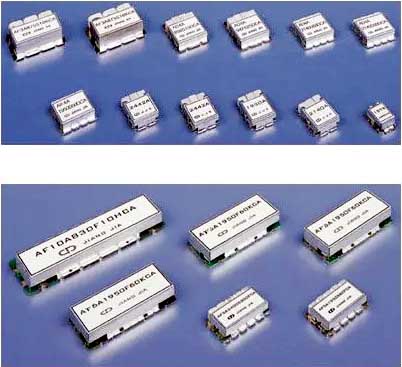
An important feature of dielectric filters is that they are easy to miniaturize. Practice has proved that dielectric filters made of ceramic materials with high dielectric constants are used. Its volume can reach only a fraction of the cavity resonator type filter. More importantly, the variation of the resonant frequency of the dielectric filter with temperature can be controlled within a small range. Because the research on ceramic materials has been quite in-depth nowadays, and the required ceramic properties can be obtained by adjusting the formula of ceramic materials.
A resonant cavity refers to a component that can store electromagnetic energy, electric field energy and magnetic field energy, and it can be converted according to a certain time, which is called an oscillation process. The frequency of oscillation is called the resonant frequency. We often come into contact with electromagnetic resonators. The simplest structure is a low-frequency circuit of inductance L and capacitance C, which can be connected in series or in parallel. Two electronic components store energy, electrical energy and magnetic energy, and resonance converts energy between inductance and capacitance. In the microwave frequency band, the low-frequency circuit LC resonant circuit can no longer be applied. Traditional resonators are generally metal cavities, in which magnetic field energy and electric field energy are converted to each other. An electromagnetic resonator is a structure composed of electromagnetic energy oscillating within a limited range. Dielectric resonators are used as microwave filters. These dielectric resonators are made of materials with higher dielectric constants, and ceramic dielectric materials have the advantages of low loss and good electromagnetic properties.

Basic parameters of dielectric filter
The index of the filter can describe the frequency response characteristic of the filter vividly. For the design of microwave filters, the indicators that usually need to be considered are the following:
1. Working frequency: It is the passband frequency range of the filter, and there are two ways to define it;
① 3dB bandwidth: when the minimum loss point of the passband (the highest point of the passband transmission characteristic) is moved down by 3dB, the measured passband width;
This definition is a classic definition, without considering insertion loss, and is rarely used in engineering.
② Differential loss bandwidth: The bandwidth measured when the insertion loss is satisfied; this definition is relatively strict and is commonly used in engineering.
2. Center frequency: the center frequency point of the passband of the filter.
3. Relative bandwidth: the ratio of the absolute bandwidth of the filter to the center frequency f0.
4. Insertion loss: due to the intervention of the filter, the loss introduced in the system is expressed by the ratio of the load power before the network inserts the filter to the load power after the insertion; It can be described quantitatively with S21 parameters.
5. Return loss: The ratio of the input power to the reflected power can be described quantitatively by the S11 parameter. dB is the unit of measurement. The return loss characterizes the standing wave characteristics in the passband, and the matching with the external circuit is generally considered to be at least greater than 10dB.
6. Ripple coefficient: the change of the frequency response function in the passband of the filter, the size of the ripple coefficient is equal to the difference between the maximum amplitude and the minimum amplitude of the frequency response picture number.
7. Rectangular coefficient: Describes the attenuation degree of the filter to out-of-band signals. The steeper the transition band, the better the selectivity.
8. Quality factor Q value: The filter quality factor describes the frequency selectivity of the filter, which is defined as the ratio of the average energy storage of the filter to the energy loss per cycle at the resonant frequency point.
9. Group delay: The physical size of the microwave filter is in the same order of magnitude as the wavelength of the signal in the passband, or even larger than the wavelength of the signal in the passband. The phase of the signal inside the filter is no longer constant, the phase of the signal passing through the filter changes.
10. Parasitic passband: Since the microwave filter uses a distributed parameter element, the frequency response characteristic of the distributed parameter transmission line changes periodically. As the operating frequency increases, the inductive and capacitive properties of these components will transform, so a passband will appear in the stopband. This passband is the parasitic passband.
11. Transmission zero point: Transmission zero point, also known as attenuation pole or notch point, refers to an obvious sink point in the transition section from the pass band to the stop band. The presence of transmission zeros means that the out-of-band rejection of the filter is very good.
Part No. | Center frequency (MHz) | Bandwidth (MHz) | Insertion loss (dB) max | Fluctuation (dB) max | Maximum standing wave | Suppression (dB) min (MHz) | size Width * Length * Height | application |
SRM830F3R10SA | 830.0 | fo±5 | 3.5 | 1.0 | 2.0 | 28(fo ± 40) | 12*9*4.0 | CHINA CDMA |
SRM875F3R10SA | 875.0 | fo±5 | 3.5 | 1.0 | 2.0 | 28(fo ± 40) | 12*9*4.0 | |
SRP830F4R10SB | 830.0 | fo±5 | 3.5 | 1.0 | 1.5 | 40(fo ± 40) | 13*12*5.0 | |
SRP875F4R10SB | 875.0 | fo±5 | 3.5 | 1.0 | 1.5 | 40(fo ± 40) | 13*12*5.0 | |
SRM902K5N25FA | 902.5 | fo±12.5 | 2.0 | 1.0 | 1.5 | 40(fo+32.5) | 30*8.3*6.5 | GSM |
SRM947K4N25FA | 947.5 | fo±12.5 | 2.0 | 1.0 | 1.5 | 40(fo-32.5) | 25*8.3*6.5 | |
SRP902N10R25FA | 902.5 | fo±12.5 | 3.0 | 1.0 | 1.5 | 65(fo ± 32.5) | 42*17*9.0 | |
SRP902N10R25FA | 947.5 | fo±12.5 | 3.0 | 1.0 | 1.5 | 65(fo ± 32.5) | 42*17*9.0 | |
SRP897N10R35FA | 897.5 | fo±17.5 | 5.0 | 2.5 | 1.5 | 30/25(fo ± 25) | 42*17*9.0 | E-GSM |
SRP942N10R35FA | 942.5 | fo±17.5 | 5.0 | 2.5 | 1.5 | 25/30(fo ± 25) | 42*17*9.0 | |
SRM1950F3R60SA | 1950.0 | fo±30.0 | 2.5 | 1.0 | 1.5 | 40(fo+160) | 11.5*6*3.9 | W-CDMA |
SRM2140F3R60SA | 2140.0 | fo±30.0 | 2.5 | 1.0 | 1.5 | 40(fo-160) | 11.5*6*3.9 | |
SRM1747B3R75SA | 1747.5 | fo±37.5 | 3.0 | 1.0 | 1.8 | 25(fo+132.5) | 5.7*4.4*2.0 | DCS |
SRM1842B3R75SA | 1842.5 | fo±37.5 | 3.0 | 1.0 | 1.8 | 30(fo-132.5) | 5.7*4.2*2.0 | |
SRM1747F5N75FA | 1747.5 | fo±37.5 | 3.5 | 2.0 | 1.8 | 20(fo+57.5) | 13.5*6.5*4.0 | |
SRM1842F5N75FA | 1842.5 | fo±37.5 | 3.5 | 2.0 | 1.8 | 25(fo-57.5) | 13.5*6.5*4.0 | |
SRC3420F4R40SA | 3420.0 | fo±20.0 | 2.5 | 0.5 | 1.5 | 35(fo ± 100) | 15.0*5.7*4.5 | MMDS |
SRC3520F4R40SA | 3520.0 | fo±20.0 | 2.5 | 0.5 | 1.5 | 35(fo ± 100) | 15.0*5.7*4.5 | |
SRM3462D3R27SA | 3462.5 | fo±13.5 | 3.0 | 1.0 | 1.5 | 15(fo ± 86) | 8.3*7.5*3.0 | |
SRM3562D3R27SA | 3562.5 | fo±13.5 | 3.0 | 1.0 | 1.5 | 15(fo ± 86) | 8.3*7.2*3.0 | |
SRM3450D3R100SA | 3450.0 | fo±50.0 | 2.3 | 1.0 | 1.5 | 12(fo + 150) | 8.3*4.5*3.0 | |
SRM3550D3R10SA | 3550.0 | fo±50.0 | 2.3 | 1.0 | 1.5 | 15(fo - 150) | 8.3*4.5*3.0 | |
SRP1690F4R20SA | 1690.0 | fo±10.0 | 2.5 | 0.5 | 1.5 | 45(fo + 70) | 13*12*5.0 | K-PCS |
SRP1705F4R40SA | 1705.0 | fo±10.0 | 3.0 | 0.5 | 1.5 | 45(fo + 70) | 13*12*5.0 | |
SRP1765F4R30SA | 1765.0 | fo±15.0 | 2.5 | 0.8 | 1.5 | 30/45(fo ± 75) | 13*12*5.0 | |
SRP1765F4R30SB | 1765.0 | fo±15.0 | 2.5 | 0.8 | 1.5 | 45/30(fo ± 75) | 13*12*5.0 | |
SRP1760F4R20SA | 1760.0 | fo±10.0 | 2.8 | 0.5 | 1.5 | 30/45(fo ± 75) | 13*12*5.0 | |
SRP1850F4R20SA | 1850.0 | fo±10.0 | 2.8 | 0.5 | 1.5 | 30/45(fo ± 75) | 13*12*5.0 | |
SRP1880N10N60FA | 1880.0 | fo±30.0 | 4.0 | 2.0 | 1.5 | 50(fo ± 50) | 43.5*13*9.0 | US-PCS |
SRP1960N10N60FA | 1960.0 | fo±30.0 | 4.0 | 2.0 | 1.5 | 50(fo ± 50) | 43.5*13*9.0 |