
China Mains Filter
What is a power filter?The power filter is a filter circuit composed of capacitors, inductors and resistors, also known as "power EMI filter", a passive bidirectional network, one end of which is the power supply, and the other end is the load. The principle of the power filter is an imped
What is a power filter?
The power filter is a filter circuit composed of capacitors, inductors and resistors, also known as "power EMI filter", a passive bidirectional network, one end of which is the power supply, and the other end is the load. The principle of the power filter is an impedance adaptation network: the greater the impedance adaptation between the input and output sides of the power filter and the power and load sides, the more effective the attenuation of electromagnetic interference. The filter can effectively filter the frequency point of a specific frequency in the power line or frequencies other than this frequency point to obtain a power signal of a specific frequency or eliminate a power signal of a specific frequency.
Introduction to power filter
A power filter is an electrical device that effectively filters out a specific frequency point in the power line or frequencies other than this frequency point. The function of the power filter is to obtain a power signal of a specific frequency or eliminate a power signal of a specific frequency by connecting the power filter to the power line.
Utilizing this feature of the power filter, a square wave group or composite noise passing through the power filter can be turned into a sine wave of a specific frequency.
Filters for high-power power supplies such as Satons, UBS, and frequency converters will generate a large amount of harmonic currents. Active power filters (APF) must be used for such filters. APF can filter the 2~50 harmonic current.
 |  |  |
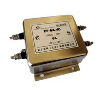
| Filtro de alto rendimiento AC monofásico Los circuitos de filtro de modo común de dos etapas, modo común de una etapa y modo diferencial de una etapa o modo común de dos etapas y modo diferencial de una etapa tienen buenas características de supresión de interferencias de modo común y modo diferencial. Puede suprimir eficazmente varias interferencias transitorias de alta frecuencia. Se puede personalizar de acuerdo con diferentes rendimientos, corriente de trabajo, voltaje, dimensiones externas y métodos de terminación. ▲ Voltaje nominal: 115/250 VCA ▲ Frecuencia de línea: 50/60 Hz ▲ Corriente de fuga::<1.0 mA(@250VAC/50Hz) ▲ Voltaje de prueba: Línea—Línea 1450 VCC, 1 min. Línea—Tierra 1500VAC, 1 min. ▲ Rango de temperatura: -25 ℃ ~ + 85 ℃ | Filtro de CA trifásico de tres hilos Suprime las interferencias de radio transmitidas a lo largo de la línea eléctrica, adecuado para equipos electrónicos de potencia que requieren una fuente de alimentación trifásica de cuatro hilos. Como fuente de alimentación conmutada, UPS, equipos de comunicación, equipos médicos y equipos de accionamiento eléctrico. Se puede personalizar de acuerdo con diferentes rendimientos, corriente de trabajo, voltaje, dimensiones externas y métodos de terminación. ▲ Tensión nominal: 440VAC ▲ Frecuencia de trabajo: 50/60Hz ▲ Corriente de fuga: <2,0 mA(@250VAC/50Hz) ▲ Tensión de prueba: Línea-línea: 1450VDC, un minuto Línea-tierra: 1500VAC, un minuto | filtro de CC Diseñado para suprimir la interferencia de la línea de alimentación de CC. Tamaño pequeño, peso ligero, rendimiento fiable, precio bajo y otras ventajas. Se puede personalizar de acuerdo con diferentes rendimientos, corriente de trabajo, voltaje, dimensiones externas y métodos de terminación. ▲ Tensión nominal: 100 VCC ▲ Tensión de prueba: Línea-línea: 200VDC, un minuto Línea-tierra: 500 VCC, un minuto ▲ Rango de temperatura: -25 ℃ ~ + 85 ℃ |
Installation of mains filter
There should be no electromagnetic coupling path in the power supply filter
① The power input line is too long;
② The input line and output line of the power filter are too close.
Both of these are incorrect installation methods. The essence of the problem is that there is a significant electromagnetic coupling path between the filter's input wires and its output wires. In this way, the EMI signal existing at one end of the filter will escape the suppression of the filter, and will be directly coupled to the other end of the filter without being attenuated by the filter. Therefore, the input and output of the filter must be effectively separated.
In addition, as in the above two types, the power filter is installed inside the equipment shield. The EMI signals on the internal circuits and components of the equipment will be directly coupled to the outside of the equipment by generating EMI signals on the (power) terminal leads of the filter due to radiation. Loss of equipment shielding suppression of EMI emissions generated by internal components and circuits. Of course, if there is an EMI signal on the filter (power supply), it will also be coupled to the components and circuits inside the device due to radiation, thus destroying the suppression effect of the filter and shield on the EMI signal. So it won't work.
2. Do not bundle the cables together
Generally speaking, when installing a power filter in an electronic device or system, it should be noted that when bundling equipment cables, the wires at the filter (power) end and (load) end must not be bundled together. Because this will undoubtedly intensify the electromagnetic coupling between the input and output terminals of the filter, seriously destroying the ability of the filter and equipment shielding to suppress EMI signals.
3. Try to avoid using long ground wires
It is advisable that the length of the wire connecting the output end of the power filter to the inverter or the motor should not exceed 30 cm.
Because an excessively long ground wire means greatly increasing the ground inductance and resistance, it will seriously damage the common mode rejection ability of the filter. A better method is to securely fasten the filter shield to the enclosure at the equipment power inlet with metal screws and star spring washers.
4. The input line and output line of the power filter must be separated
The input line and output line of the power filter must be separated, and parallel connection should not be avoided, so as not to reduce the efficiency of the filter.
5. The power filter shell and the chassis shell must be in good contact
The special filter metal shell of the inverter must be in good surface contact with the chassis shell, and the grounding wire must be connected well.
6. The connection line of the power filter should be twisted pair
It is better to use shielded twisted pair for the input and output connection lines of the power filter, which can effectively eliminate some high-frequency interference signals.
Common Mistakes in Power Filters
In the process of experimental testing, we often encounter such situations:
Although the design engineer has connected a power filter to the power line of the equipment, the equipment still cannot pass the "conducted interference voltage emission" test. The engineer suspected that the filtering effect of the filter was not good, and he kept changing the filter, but still could not get the desired effect.
The reasons for analyzing equipment exceeding the standard are nothing more than the following two aspects:
1) The interference generated by the equipment is too strong;
2) Insufficient filtering of the device.
For the first case, we can take measures at the interference source to reduce the intensity of the interference, or increase the order of the power filter to improve the filter's ability to suppress interference. For the second case, in addition to the poor performance of the filter itself, the installation method of the filter has a great influence on its performance. This point is often overlooked by design engineers. In many tests, we were able to get the device to pass by simply changing how the filter was installed. The following are some examples of the impact of common filter installation errors on filter performance.
input line too long
After the power cord of many devices enters the chassis, it is connected to the input end of the filter through a long wire. For example, the power cord enters from the rear panel of the chassis, travels to the power switch on the front panel, and returns to the rear panel to connect to the filter. Or the installation position of the filter is far from the inlet of the power line, resulting in too long leads. As shown in Figure 1.
Because the lead from the power inlet to the filter input is too long, the electromagnetic interference generated by the equipment is re-coupled to the power line through capacitive or inductive coupling, and the higher the frequency of the interference signal, the stronger the coupling, resulting in the failure of the experiment.
Parallel trace
Some engineers often bundle the cables together in order to make the wiring inside the chassis beautiful, which is not allowed for power cables. If the input and output lines of the power filter are routed in parallel or bundled together, due to the distributed capacitance between the parallel transmission lines. This wiring method is equivalent to connecting a capacitor between the input and output lines of the filter, providing a path for the interference signal to bypass the filter, resulting in a significant drop in filter performance, and even failure when the frequency is high ( as shown in picture 2). The size of the equivalent capacitance is inversely proportional to the wire distance and directly proportional to the length of the parallel traces. The larger the equivalent capacitance, the greater the impact on filter performance.